When I was checking out the runout on the various chucks and collets recently, I continued to be irritated by a strange creaking noise from the general area of the belt drive between the motor and the spindle. At high speeds it's barely noticeable but at low speeds, it's evident as a bizarre creaking, crackling noise. I made a short video of the head with one of the vent panels removed. This is at 25 rpm and although you might argue I'll never be operating the motor at such a low speed, the problem is there nonetheless:
I've never been inside this part of the machine, partly due to the sheer weight of the motor and the size / weight of the belt housing. However, there are several reasons for wanting to dive in and take a closer look:
- The belt doesn't look long for this world. I'm pretty sure I removed some fragments of the belt previously, which suggests that it's starting to delaminate. I'm also guessing that the noise is coming from the belt itself.
- I'd like to check out the various bearings, given the state of the spindle bearings that had to be replaced previously. Its also heaving with heavy grease and could doubtless do with a cleanup.
- I'd like to clean up and examine the reduction gears. In the process this will also allow me to determine the reduction ratio from high (direct drive) to low (2 stage gear reduction).
- I will be able to check the pulley ratio between the motor and the spindle. Hitherto I've assumed it was 1:1 and although it's clearly close to that (by eyeballing the motor and spindle pulleys), I may as well get it right.
- If possible I'd like to fit a couple of proximity sensors up against the spindle gear that will provide a quadrature signal so I can get a spindle speed and direction signal to the CNC controller. That would enable rigid tapping and allow me to capture the actual speed.
- I will need to remove the motor and belt housing if I am ever to remove the machine from the workshop through the 7' high roller door. It's too high otherwise. Best to have a dry run now rather than in the heat of a house move.
But first, there is the slight issue of the weight of the motor (40-50kg?) and pulley housing (30-40kg?). They are pretty large chunks of metal. And both are mounted on top of the head, about 2m from ground level. Far too heavy to remove by hand, so I'll need to use the engine crane.
In its standard setup, the maximum extension isn't quite enough to reach above the motor. However, I've been meaning to extend the arm for some time. The current maximum is rated for 100kg and I reckon I could probably support 50kg or so at a further 20cm or so:

It just required a couple of extra holes in the hollow boom. That allowed me to bring the motor down in a controlled(!) fashion:


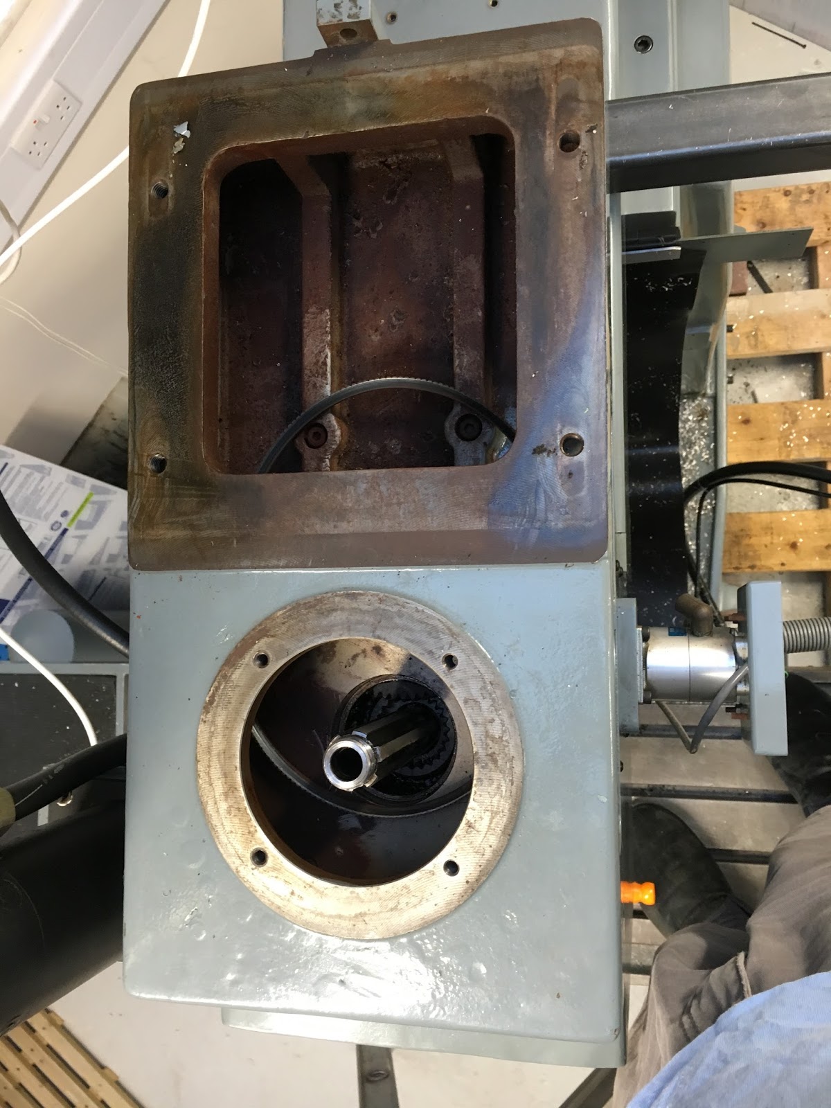
This exposed the pulley housing:
The pulley housing was fastened to the head by 6 bolts from inside. But even when I'd finally managed to extract them, there was a spacer piece between the housing and the head, holding the housing in place. God knows why that is fitted. It's only a 3kW motor, so the forces involved are pretty modest. The spacer is hollow and held to the head by 4 awkward bolts and the housing by another 4 awkward bolts. I managed 6 of them but the final 2 (the furthest bolts into the head) were not going to happen. It wasn't helped by some fat clot fitting a large box section in front of the opening:

Drilled a couple of 10mm holes above them and managed to undo them with a long Allen key. When it comes to reassembly, I simply won't be refitting the spacer and nobody will be any worse off.


I was then able to remove and lower the pulley housing:

This exposed the cover on the gear housing which came off easily with 4 bolts and 2 dowel pins:

Within the gear housing are the 4 gears that form the reduction stage (ratio TBA). It all looks pretty good once you see past the grease. The yoke moves the gear cluster up and down, either engaging direct drive or engaging the 2 stage reduction gears. The "female" gear is the simple method for achieving a direct drive - the motor (input) gear mates directly with the "female" gear when the yoke is slid upwards. You are looking down at the yoke in its normal orientation. The large, first stage reduction gear would normally be sitting above the 4-splined idler and is always engaged with the input (motor) gear:

On the underside is the second stage reduction gear. This mates with the large output gear. The teeth are specially shaped to help with the engagement. The first stage output gear is always engaged with the input (motor) gear, so the 4-splined shaft at the bottom of the picture is always rotating. When the yoke is in the lower position (ie brought closer to the camera), it engages with the final output gear on the spindle, giving the low ratio - 22t:

This is the underside of the circular cover with the first reduction stage still mounted. The end of the shaft you can see is normally supported by a taper roller bearing. I assume there is another one hidden behind the gear.

Here is the final reduction gear which is splined to the output (spindle). I hope to pick up the gear teeth using a couple of proximity sensors. There seems to be plenty of space - 48t:

For completeness, here are the other gears in closeup, so I can count the teeth. Motor (input) gear - 23t:

First stage reduction gear (driven). It looks as if it may be Tufnol (to reduce gear noise). It is permanently engaged ie there is no need for engagement / disengagement, so no need for hardened steel teeth - 64t:

The motor and spindle pulleys are a surprise. They seem to be 60 degree vee belt pulleys. Most vee belts are 40 degrees - WTF?? I'll probably remove them and remachine them at 40 degrees, not least as there is a fair bit of wear evident.

I can now see the gears quite clearly, which allows me to count the teeth and deduce the reduction ratio:
- First reduction stage input gear - 23t
- First reduction stage output gear (Tufnol) - 64t
- Second reduction stage input gear - 22t
- Second reduction stage output gear (on spindle) - 48t
Overall ratio: 64/23 x 48/22 = 6.07:1
Strange ratio! But with 6000 rpm high spindle speed, the max speed in low would be 1000 rpm. That gives a 6:1 range requirement for the motor. Conversely it suggests a min speed of about 170 rpm if the motor is limited to a 6:1 range. Note that in fact the brochure species 1-6000 rpm
Finally, the motor pulley diameter is actually 85mm and the spindle (driven) pulley is 92mm, so there is a reduction of about 8% (the neutral axis of these belts is close to the circumference). Not a great deal different to 1:1.
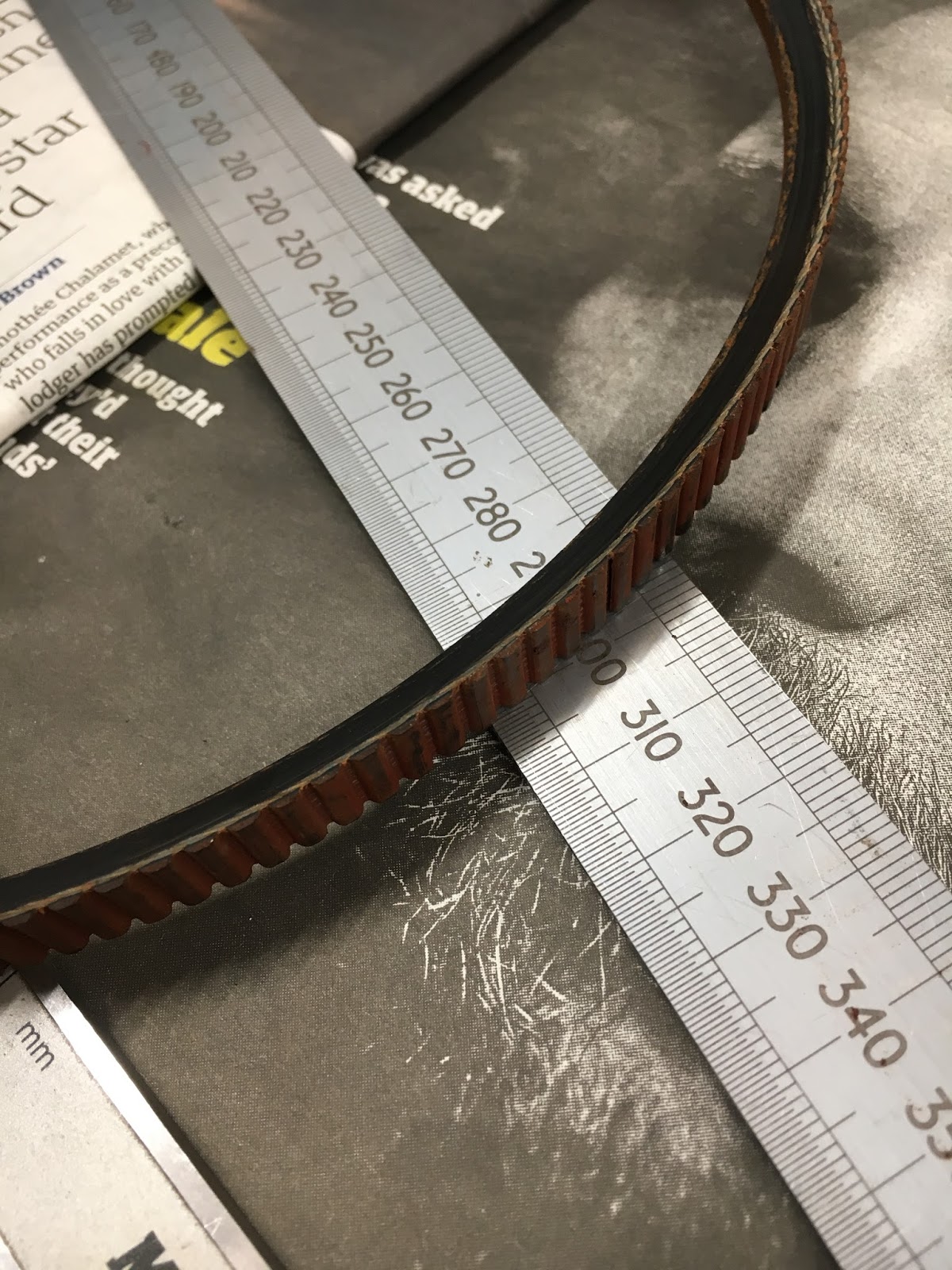
The length of the belt measured on the outer circumference (which is close to the neutral axis, as noted) is about 770mm. Sounds like an SPZ772 profile, using Fenner terminology.
BUT: Bizarrely, as noted above, the pulley vee slot has an angle of 60 degrees (WTF???). I've never seen this before - it's almost invariably 40 degrees. There is a fair bit of wear evident in the pulley faces, so I may end up remachining them - and in the process reverting to a more conventional vee shape.
I must dig out the photos of the spindle assembly to see how / if this pulley comes off the spindle assembly easily:
Hmm. After much searching, I see that I haven't dismantled the input shaft assembly. I'll just have to go in blind.....


No comments:
Post a Comment